If you mean my comment about the "Suicide Lead", you said "
I now run 2 seperate circuits and couple them together by a lead with a plug on each end when wild camping only so that I can use all the sockets in the van fed from the inverter. ". A plug on each end means that you will have 240V on exposed pins if one end is left unplugged. There is a very good reason why a supply is always provided in the format of a 'female' socket whose connections are covered and cannot come into contact with fingers!
Often people use these kind of leads (and also make hookup leads with a plug outlet to match the incorrectly fitted hookup socket (which MUST be a hookup PLUG)) and say 'oh, it's safe as I know how to use it safely' but along comes someone else in the van on a trip or on a campsite and BOOM! (and damage to an
inverter could be the least of your worries

)
Using a lead like that will also put mains 240V and the
inverter 240V output together should someone plug into the mains unwittingly (like your son did already). This will likely damage not only the
inverter but devices plugged into sockets as you are feeding them two different mains sources with almost certainly different voltages and very out of sync sine waves. A bad idea!
How else would I suggest?
Well, #1 is to immediately cut the plugs of that lead so you never use it again
#2 - You need to have a setup so the output of an
inverter can never be connected to the mains hookup supply (it doesn't matter if there is an MCB or an RCD between - you just don't do that!)
How to do #2?
You could have the EHU hookup cable that goes to the CU going through a plug and socket first. and then you could feed the CU with either the EHU (CU plug into EHU internal Socket) or
Inverter (CU plug into
Inverter Socket).
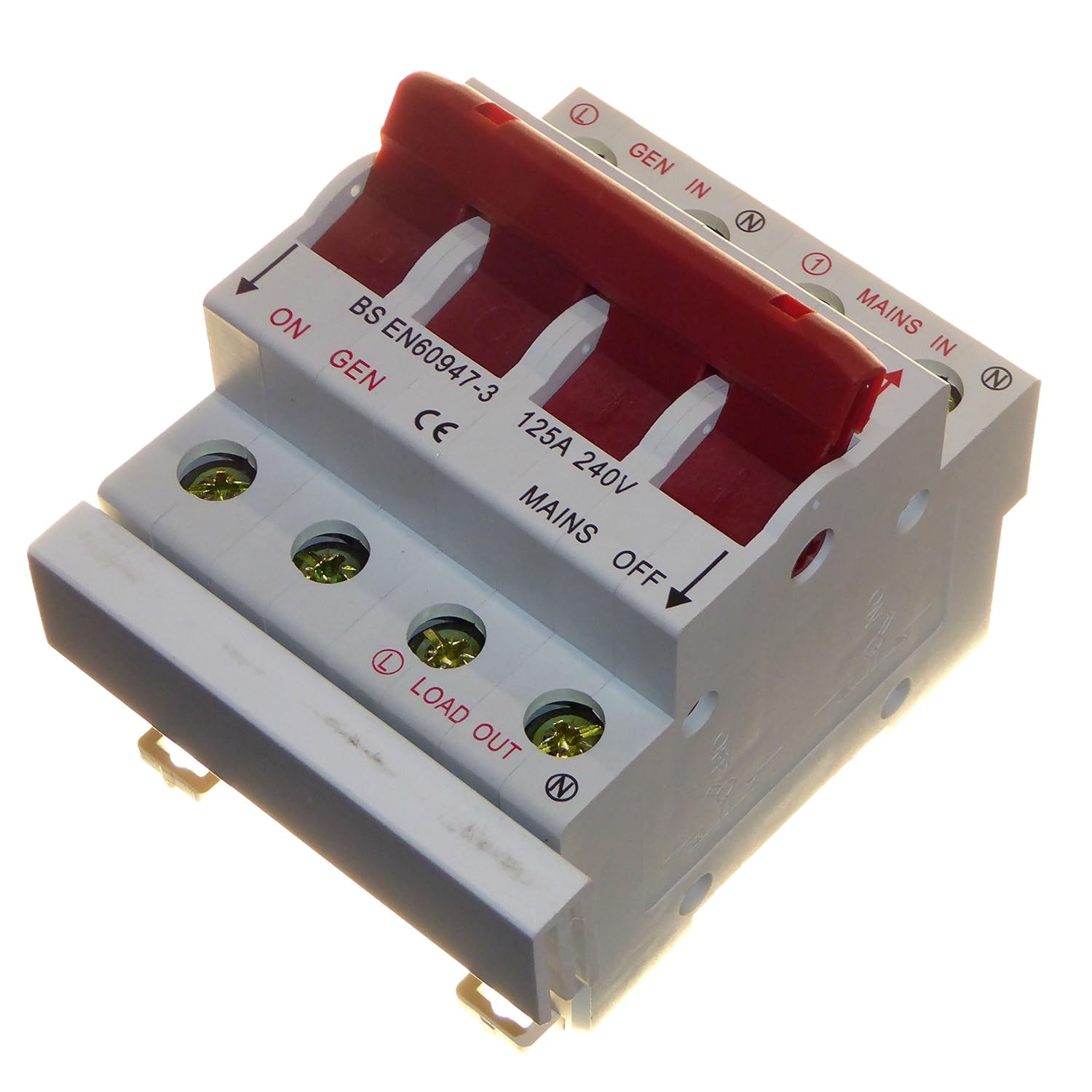
You cou
ld use a
Changeover Switch (see picture for example) instead of separate sockets to make it a cleaner operation - I have one of these fitted in my conversion that I use as a polarity reverser, but they are usually used to feed an installation from 1 of two different sources (in your case, EHU or
Inverter)
The one shown here fits in a CU. you can also get ones that are standalone.
Other options include using a Contactor, which is a 240V Relay that senses when a supply is live and switches over to it. This is a good option for an automatic transfer between an
Inverter (the default) and EHU (goes to EHU whenever that is live).
So basically lots of options, but all those are safe. A
Suicide Lead is not!
Last thing to remember ... when setting up the transfer, remember to avoid having the Mains
Battery Charger fed by the
Inverter! It won't cause any damage, but will just waste power using
battery energy to charge the same
battery