B2B Battery 2 Battery charger

What are the two 'Coil +Diode' units? added in? not sure how they come into play?

I don't know what relies on what in terms of the existing electrics, but this circuit will disconnect the connection between J2 and Leisure Battery ....

View attachment 50825

The Coil+Diode represent the coil in a relay, in my business we would always put a diode across the relay coil, it snubs the high voltage spikes when the supply is removed from the coil.

In my circuit the Double Pole relay is doing a similar job as your Low-Power Relay and additionally enabling the B2B. This relay really isn't required in hindsight.

The Single Pole relay is doing the same as your High-Power Rely.

Relays are reliable and easily changed should they fail.

I am grateful for your circuit diagram, thank you. What software do you use to create these drawings?

I am still considering the use of a single 100 amp diode in the feed between Starter Battery and J1. There will be a small voltage drop, approximately 0.75 volts across the diode.

With the engine running the higher B2B voltage can't feed back to the SB. The fridge would get a slightly elevated voltage which may improve its efficiency. A drawback could be that the B2B sees a slight change as the fridge thermostat clicks in and out.

I would appreciate your comments on the attached circuit, there must be a flaw I haven't seen yet.
 

Attachments

  • diode_circuit.pdf
    13.2 KB · Views: 28
I think I have exactly this (xsilvergs Tuesday 1037 & Wildebus 4.35pm today) but I fitted it 6 years ago after consulting my father who was an electronic engineer and now I can't recall the detail.

I have a Rapido and cbe system, 2 110A gel batteries, Votronic 45A b2b with temperature sensor and 80w solar. The big relay is a heavy duty changeover Durite 072870, the control relays are n/c Durite 072072. The b2b is started off the D+ and wird with the biggest cable that fitted the terminals (25mm?).

So, in operation the leisure batteries are only connected to the b2b charger; the fridge, truma dump valve and all internal power works as normal. The cbe display will show only vehicle battery voltage on both vb and leisure battery settings and the amps shown will be about zero, I fitted a separate nasa battery monitor to show b2b charging current which is also much more accurate the rest of the time.

I do recall being concerned that the dump valve might operate during changeover but it never has.

The solar panel is also isolated by the relay.

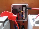
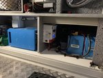
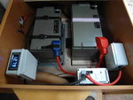
Never had a single problem.battery compartment new fit.jpgb2b relay and busbar.jpg
 
Last edited:
The Coil+Diode represent the coil in a relay, in my business we would always put a diode across the relay coil, it snubs the high voltage spikes when the supply is removed from the coil.

In my circuit the Double Pole relay is doing a similar job as your Low-Power Relay and additionally enabling the B2B. This relay really isn't required in hindsight.

The Single Pole relay is doing the same as your High-Power Rely.

Relays are reliable and easily changed should they fail.

I am grateful for your circuit diagram, thank you. What software do you use to create these drawings?

I am still considering the use of a single 100 amp diode in the feed between Starter Battery and J1. There will be a small voltage drop, approximately 0.75 volts across the diode.

With the engine running the higher B2B voltage can't feed back to the SB. The fridge would get a slightly elevated voltage which may improve its efficiency. A drawback could be that the B2B sees a slight change as the fridge thermostat clicks in and out.

I would appreciate your comments on the attached circuit, there must be a flaw I haven't seen yet.
sounds like on the same page :)

I use Visio for wiring diagrams. That particular one was just a few blocks so could be easily done in something like Powerpoint or even paint.net though.
 
sounds like on the same page :)

I use Visio for wiring diagrams. That particular one was just a few blocks so could be easily done in something like Powerpoint or even paint.net though.

Visio, I see that's Microsoft, I use Linux and used LibreOffice Draw, it's just a faff writing in all the terminal numbers, hence none :)
 
Visio, I see that's Microsoft, I use Linux and used LibreOffice Draw, it's just a faff writing in all the terminal numbers, hence none :)
they are just separate text boxes dropped on top :)
 
Is this an alternative to the relay option for B2B charging?

The Starter Batteries main job while driving is to supply power to charge the Leisure Battery (LB) and power the fridge. My idea which I'm putting out for comments is this. Disconnect the Starter Battery (SB) by removing the lead to J1. Use a B2B to charge the the LB from the SB and use a modified sine wave (MSW) inverter powered from the SB whilst driving, to power the AC within the van.

The fridge should be happy, it's low power control system is being powered by the LB and its resistive heating element should be happy on the MSW.

RE1's contacts would be closed while driving so any small loads, marker lights etc would be powered from the LB.

Your thoughts would be most welcome.
 
What would you be gaining by having an inverter going to the fridge rather than a relay?
I guess because the Fridge is running on 240V AC rather than 12V DC it runs as a proper fridge rather than in a coolbox-style maintenance mode. Is that correct? If that is the case, than could be worthwhile?
There are a couple of caveats though... You need to be able to have the inverter come on and off automatically to avoid this being an annoyance. If you leave the inverter switched on, it will drain the starter. If you switch it on manually you can easily forget (I could anyway) to either switch it ON in the start of a trip, or OFF when stopping the engine. If you used a relay to transfer DC power to it on engine startup, turning the engine off will cut power to the inverter when it may need power for cooling fans (so could overheat potentially?)

You could have an inverter the Leisure Battery side to do precisely the same thing which maybe more useful overall? But the same caveats apply.

Or ... You could use an inverter to both do what you are thinking AND be part of a B2B AS WELL! You could send 240V to the Fridge AND to a Smart 240V Charger working as a B2B (this thread might illustrate that idea... https://motorhomer.com/threads/charging-your-leisure-batteries-on-the-move.39016/page-2#post-106018)

I wasn't looking gain much just get around having a relay connecting and disconnecting the LB. It also means the B2B wouldn't be trying to charge the SB. I have looked for an inverter which has an enable/disable function using a 12v/0v signal but not seen anything yet. I still wonder about disconnecting J1 from the SB as above and letting the B2B charge the LB and run the fridge while driving. I would like to log some data of the fridges 12v current consumption while driving, it may not be as bad as I imagine. Have you ever looked into this?

I've read many of your post which are pretty thorough and a good source of information, and I like your all electric van idea.

I see Gadget John is about to fit a Victron B2B (Orion something I guess), I'm interested in how his fit goes.
 
I have never used a 3-way (12V/Gas/240V) fridge so I don't know how much power they use, but my understanding is that in 12V mode they are not a lot better (maybe worse?) than a basic Coolbox - hence the reason why they only get power for cooling when the engine is running.

There are no economical inverters that will auto enable/disable on the presence of a charge level voltage. This would be tricky to implement as the loading on an inverter will cause the battery voltage to drop.
Enginre starts ===> Battery gets a charge ===> Voltage rises ===> Inverter turns on ===> Voltage drops ===> Inverter detects non-charge voltage level ===> Inverter turns off ===> Load removed so Voltage rises ... and the cycle goes round.
The way I get round that is to fit a kit like this (https://wildebus.com/store/index.php?route=product/product&path=69&product_id=62), and add in a cheap VSR device like a TEC3M (used as an auto on-off for Fridges in fact) to control the high-power relay.

The new Victron B2B - basically a multi-stage Orion DC-DC converter - has been long overdue in the Victron Product Range I would say, and is pretty good value as Victron kit goes. One annoyance on it - and why I am not bothering looking it at the moment personally - is it is missing the VE.Direct connectivity for the Victron Venus system for data logging, however it does have the bluetooth connectivity though, so some useful info can be seen there I am sure.
 
How safe and is it legal to have 240v in a moving vehicle?
The emergency services will expect lpg hazard but cutting through mains cables is not something they'd be avoiding.

For 3 way fridges there's not a lot of difference between the heater elements driving the system - it's the wattage that precludes 12v without the help of the alternator.
 
Last edited:
How safe and is it legal to have 240v in a moving vehicle.
The emergency services will expect lpg hazard but cutting through mains cables is not something they'd be avoiding.

For 3 way fridges there's not a lot of difference between the heater elements driving the system - it's the wattage that precludes 12v without the help of the alternator.

Interesting point regards Emergency Services.
 
Though I would say the trip hazard from the mains cable on the van to the grid socket could be a problem ;)

I'd like to see any valid* information that suggests that having an inverter running in a moving vehicle is not legal.


*I say 'valid' as if you search the internet enough you can find "data" to back up any theory anyone can come up with.
 
Wow that was a strain to keep up with and I'm not sure I did. It seems far to complicated for it own good.
Before I went solar I also used the alternator to power everything whilst driving. Simple solution avoiding anything that might automatically fail.
Big inverter with a big isolator switch connected to the engine batteries. (24volt) The inverter mains ran the fridge and battery charger for the leisure batteries whilst driving with a plug and socket inline.
When running the fridge from the leisure battery inverter which was connected to another socket by the first one, you simple pulled the plug from one and put it in the other.
 
One point on the Sterling B2B 1260. I have twin 90ahr Victron lithium batteries. The B2B 1260 will supply about 45A no problem initially but will reduce the charge rate significantly when the temperature of the B2B unit rises towards its 80degC limit. Even though it has an internal fan this is not up to coping with 40A+ charge rates. I added an extra fan with ducting to take cooler air from outside the vehicle. This is connected after the ignition from the vehicle electrical system so it only runs when the ignition switch is on. I can now get 40A+ even in warm summer temperatures.
 
Phase one is complete.

I've changed the wiring from the Solar Controller to the battery. The original routing was through the Nordelettronica unit but with the additional solar panels there was the possibility of blowing the standard fuse and worse, causing damage to its PCB. The wiring goes direct from the Solar Controller the the battery with only a 40 amp midi fuse in the way.

Part of the floor has been up, I've added conduits so when the B2B gets ordered I can pull the 16mm2 cables through.

As time is running out this project may stray into next year.
 
It is the alternator that needs worrying about unless you can protect it against overheating - especially if you are considering a Li battery
 
It is the alternator that needs worrying about unless you can protect it against overheating - especially if you are considering a Li battery
That is one of the reasons I use a B2B with my Li. It protects the alternator as well as looking after the battery. My Votronic VCC1212-45 has adjustable in and out limits. I have the in limit set to 42A so that I can safely use a 50A circuit and not overtax the alternator. The out limit can be lowered from 45A to 38A so that it can work with existing distribution equipment such as an EBL.
 
One point on the Sterling B2B 1260. I have twin 90ahr Victron lithium batteries. The B2B 1260 will supply about 45A no problem initially but will reduce the charge rate significantly when the temperature of the B2B unit rises towards its 80degC limit. Even though it has an internal fan this is not up to coping with 40A+ charge rates. I added an extra fan with ducting to take cooler air from outside the vehicle. This is connected after the ignition from the vehicle electrical system so it only runs when the ignition switch is on. I can now get 40A+ even in warm summer temperatures.
I've read similar things about the Sterling and also (I think) the Ring both getting hot and throttling back their charge significantly and it is a bit concerning.
I know on somne testing I did the Ablemail 30A unit ran continuously for 4 hours at full output (actually putting out 32A) with no issues and the Redarc 40A unit put out between 35A and 38A (fluctuated between that range) for slightly more than 4 hours.
What is interesting about that is neither the Ablemail OR the Redarc has ANY active cooling in the form of fans and are sealed units with no airflow within them. I guess a very clear difference in design approach? (I'll be doing a test on the Ablemail 60A B2B shortly and attaching a temperature sensor as well - the 30A unit hit 50C after 4 hours of full-on output)
 
It is the alternator that needs worrying about unless you can protect it against overheating - especially if you are considering a Li battery
Most definite!! The Li will act like a sponge when it comes to accepting charge and can easily cause issues with both existing wiring and alternator damage, but also needs to be charged at the correct voltages to get the best possible charge into the Li (especially if your van happens to be a Euro 6+ Smart Alternator).
We mainly go by 50% of the alternator output when selecting the right B2B for the job, I.e most Sevel Vans (Peugeot/Citroen/Fiat X250/290 with standard AC and manual gearbox) run at around 120A output and have built-in thermo cut outs, so we work to a max of 60A. The most we ever see going through the system is around 53.8A by the time all the cabling and installation has been upgraded to suit.
The reason for using Sterling Products is they are E Marked for road application and we have found over the many years with working with them, the back up is great (even with out of warranty issues).
Pictured is today's install where 2x Victron Lithium, Sterling BB1260 and Victron Multiplus has been installed. The Victron was happily putting in 90A on hook up and at idle speed, the B2B was at 47.4A.

Carthago ELine Li 1119.JPG
 

Users who viewed this discussion (Total:0)

Back
Top