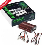
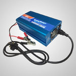
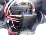
12V Transformer

Londonboii

Free Member

Messages
42
I am considering adding a 12v transformer to my system in order to be able to isolate the batteries when on Hook up and run all the 12V via a transformer. Seems a waste to be on hook up and still use the batteries when they could take the opportuniy to get a really good charge.

Will this work and is it worth doing? The transformer is 12v 300W 25A

I realise I will need to make sure to switch the transformer off when I am off hook up as I could end up running the 12v from the transformer via the inverter but I think if the selector switches are beside each other this is unlikely. Are there any other downsides I may not have considered?

Images of screenshots below although I have added the PDFs also as the images are quite blurry.

My current setup

Capture.JPG

Here is what I am suggesting, adding transformer with switch

Capture2.JPG

So I will end up with this setup

Capture3.JPG
 

Attachments

  • ADDITIONAL.pdf
    5.3 KB · Views: 4
  • REVISED.pdf
    5.4 KB · Views: 3
  • CURRENT.pdf
    5.2 KB · Views: 3
I have a halfords charger I fitted that I can switch on when on hook up. But it doesnt charge as fast as the power is used.

It's not set up to charge the vehicle batteries. The 2 of them only get charge when driving.
 
I am with @jeffmossy and @Colinsmiff on this. One decent charger designed to charge leisure batteries and maintain the 12v supply at the same time is all you need. The leisure batteries act as a reservoir if the 12v demand exceeds the supply but if you have the right capacity charger this will not be needed most of the time. However if you separate the supply circuit from the batteries then you have no buffer and I suspect you will get voltage variations as demands kick in and out. You ask ”is it worth doing?” I am not an expert but my feeling is no it is not and it might well cause problems.

My suspicion is that the Halfords charger is the weak part of your system. It is probably designed for the charging and maintenance of a car engine battery, not the continuous supply needed in a motorhome, which It has to do whilst charging and maintaining the leisure battery at the same time.
 
Understood thanks all.

Can anyone suggest a good charger thatll do this?
What size are your batteries and what type are they? That will determine how big a charger it will be worth getting.
In terms of Chargers, apart from size, you want to think about noise - if you are on hookup overnight and recharging, you don't want a fan going all night long; You can get cheap 'bargain' chargers from eBay (Trevskoda will be along with his suggestions). Personally I like the Victron BlueSmart as you can monitor and control them via a Phone App, they are silent, programmable and have a 5 year warranty.
 
Understood thanks all.

Can anyone suggest a good charger thatll do this?

I would go for a permanent installation designed to look after the 12v supply and the battery. Make sure it has a profile and settings suitable for your battery type. Here are a couple of models I have used but shop around, these sellers may not be the best sources.

Sterling has a good reputation and is very popular in the marine sector. Has a good range of selectable battery profiles.

CBE is used by many motorhome manufacturers such as Carthago, also seems to be popular with self builders. Has Lead acid and gel settings.
 
What size are your batteries and what type are they? That will determine how big a charger it will be worth getting.
In terms of Chargers, apart from size, you want to think about noise - if you are on hookup overnight and recharging, you don't want a fan going all night long; You can get cheap 'bargain' chargers from eBay (Trevskoda will be along with his suggestions). Personally I like the Victron BlueSmart as you can monitor and control them via a Phone App, they are silent, programmable and have a 5 year warranty.

+ one.
Victron isn't the cheapest but the design, engineering and manufacturing is, in my opinion, currently unbeatable. The guarantee says it all, really.
I've got Victron equipment in the Moho and it hasn't missed a photon to date.

Colin 🙂🙂🙂
 
Just to confirm, rather than repeat what others have suggested.

If your current setup doesn't have a proper multi-stage charging system, add one instead of messing with separate power supplies. But are you sure it doesn't already?

If you want to add something, add a second multi-stage charging system for your engine batteries.

Don't worry about a system that will charge the batteries in a short time. Slow charging is better for the batteries in any case. Ideally, no faster than a 20 hour rate.

If the charger can't keep up with peak power use, that's what the batteries are there for, isn't it?
 
I see a fridge as being one of the loads - presumably this is compressor driven?
As others have said a decent multi stage charger capable of delivering c10% of nominal capacity (2 batteries so 200Ah?) say 20 amps should ensure charge stays up.
The starter batteries should be ok anyway as they are on the solar circuit.
 
Last edited:
Thanks everyone. I think I'll leave the transformer idea and see how it goes now I have the solar panels on as well as the charger. Just a thought as I have the transformer.

Another question as I've posted my current wiring layout here. I just watched Luke's van life video on his 12v electrics. I believe Phil helped him with his setup. I noticed theres only 2 cables attached to the battery and 1 is just linking the batteries so really it's just 1. The one cable goes to what seems to be an enormous fuse at 200a. Which then goes to the inverter and then to the 12v fuse panel. He says his solar panels go into the 12v fuse panel, I assume the b2b does also.

If you look at my diagram, I have 5 connections directly into the battery.

Solar controller (4mm no fuse)
12v panel (4mm via a 30A fuse)
Charger (no fuse)
Inverter (manufacturer supplied cable and fuse)
Link to other battery (16mm cable)

Is my setup ok? Or is it best to go via the fuse panel?
Comments below like this

Solar controller (4mm no fuse) - SHOULD BE FUSED!
12v panel (4mm via a 30A fuse) - OK
Charger (no fuse) - SHOULD BE FUSED!
Inverter (manufacturer supplied cable and fuse) - What is the size of Cable and size of Inverter. Almost invariably the cables supplied with inverters as standard are undersized
Link to other battery (16mm cable) - SHOULD BE FUSED AT BOTH ENDS, unless they are right next to each other, in which case there should still be a fuse, but just one central one is ok.

Personally I am not a fan on having multiple leads coming off a battery terminal and the setup you describe on Lukes Van (I haven't seen it myself) sounds pretty well spot on. I use a multi-way Midi Fuse block with a separate fuse for each of the major items (mains charger, solar charger, Inverter, Split Charge (where is YOUR Split Charge connected? you don't mention it) and 12V spade fusebox) and then a single cable to the battery bank.

Question: in the diagram it looks like you have 4 batteries? one starter, one Aux, and a pair connected together - is that correct? what is the purpose of the Aux battery?
 
I assumed the solar controller would have safety measures to avoid the need for a fuse. The installation instructions dont mention a fuse. The solar controller is a ring one that is also a b2b charger so that's where the split charge element is.

I assumed similar for the battery charger. That its smart enough not to require one. This came with clamps to connect direct to the battery. I attached the wires permanently but still assumed a fuse wasnt needed or there would be one fitted out of the box for when people leave batteries charging overnight etc. Its a halfords advanced smart charger plus.

The inverter is a krieger 1100w and I will need to see what the fuse is rated at if I can tell looking at it. Again I assumed theyd know best..

The wires linking the batteries should be fused at both ends? They are sat right next to each other. The linking cables are very short really. What size fuse would be needed for this? I've not ever seen these links fused on anything I've seen.

I cant find any fuse blocks for the larger maxi or midi fuses you mention, just single ones. I have a 12v spade fuse panel for the 12v system. A fuse panel for these connections does sound a good idea and better safe than sorry I guess. And I would have all the connections going to the large fuse panel. Then just one cable to the battery and the link to the other battery?
 
Transit Vans like mine come with 2 batteries under the front seat. Ones for starting, the other (Aux) battery is for everything else.

Then I have added 2 in the back for the campervan side of things on top of these.
 
The important thing to remember is that the primary function of a fuse is to protect the cable, not what is at the other end of it. If some mishap were to short it to earth, you want a small fuse to explode, not the whole cable setting fire to the van.
If there is a power source feeding the cable, put a fuse in between. If there are two power sources, you need a fuse each end. Though a short cable between batteries that doesn't pass any mishap risks would probably be OK with one fuse.
It is a smart move to choose a fuse rating about 50% more than the max current the cable will carry, and about 50% less than the maximum current the cable could carry.
 
Last edited:
I assumed the solar controller would have safety measures to avoid the need for a fuse. The installation instructions dont mention a fuse. The solar controller is a ring one that is also a b2b charger so that's where the split charge element is.

I assumed similar for the battery charger. That its smart enough not to require one. This came with clamps to connect direct to the battery. I attached the wires permanently but still assumed a fuse wasnt needed or there would be one fitted out of the box for when people leave batteries charging overnight etc. Its a halfords advanced smart charger plus.

The inverter is a krieger 1100w and I will need to see what the fuse is rated at if I can tell looking at it. Again I assumed theyd know best..

The wires linking the batteries should be fused at both ends? They are sat right next to each other. The linking cables are very short really. What size fuse would be needed for this? I've not ever seen these links fused on anything I've seen.

I cant find any fuse blocks for the larger maxi or midi fuses you mention, just single ones. I have a 12v spade fuse panel for the 12v system. A fuse panel for these connections does sound a good idea and better safe than sorry I guess. And I would have all the connections going to the large fuse panel. Then just one cable to the battery and the link to the other battery?
Here is an example of a fuse block with multiple Midi fuse protection

Horsebox Fusebox
by David, on Flickr
The cable to the left is the single cable going to the Battery Bank.

This is another type of unit withiut the -ve busbar
1586816934227.png
I fitted this to my Starter Battery as it had around 9 separate +ve leads hanging off the +VE terminal and it was a severe mess :( . Now I have a much tidier setup and fuse protection in a much more organised manner.

Ref the Fuses generally ... I really wouldn't assume that just because something is not present (e.g. a Fuse) it is because it is not required. Fuse holders cost money so not having them saves the makers cash.
A fuse in a device protects the device. A fuse on the cable protects the cable - a different type of protection, just like in a house where a mains lead to say a TV or whatever will have a fused plug. you wouldn't bypass that fuse just because the TV has an internal fuse.

a 1100W Inverter could draw around 80A - that needs a minimum of 16mm2 cable, same as the cable that you have linking the two batteries. I can't recall the last time I got cables with an inverter and actually used them! Again it is cost-saving.
 
So on the battery link cable I would place 2 100a fuses. A fuse before each battery positive terminal?

The cable is about 200mm long. I'm not sure there's space.

I will look for a midi fuse block. I'll have to work out what size fuses to get for each connection. I see in that image he has 100a on a 120a vsr, and 40a on a 30a solar controller. Yet the cables look to be the same size.

The krieger cables are really thick. The fuse is large also and I think it is 150a but I will check.


Fusing is confusing.
 

Users who viewed this discussion (Total:0)

Back
Top