xsilvergs
Free Member
- Messages
- 240
This is how I installed a Victron Non-Isolated B2B to a 2017 Fiat Ducato Coachbuilt Motorhome fitted with a Nordelettronica NE196 Control unit. The Fiat electrical system should be similar no matter what brand of Motorhome you have.
Why did I fit a B2B? The Fiat starter battery is a flooded type lead acid battery, Roller Team fitted a single 95Ah Varta AGM battery as part of their habitation fit. A few times I had noticed that the leisure battery hadn't charged fully by the end of a drive, once was after a Motorway drive in rush hour traffic, basically a queue where the engine never really got going.
Varta recommend a Bulk charge voltage of 14.7 volt and the Fiat alternator output peaks at about 14.5 volts which by the time it gets to the leisure battery it has lost another couple of points. I will say that Roller Team have been very generous with wire sizes, other brands my be less well blessed. These days it's all about cost and weight reduction and big wires are heavy.
Delta Conversions are the UK sales distributor for Nordelettronica, I thought I'd see if they could offer any advice regards fitting a B2B, I got a single reply, "it can't be done", I asked another question but they didn't reply. Being told it can't be done made me look harder to see if I could prove them wrong. There wasn't much help on the net, one person had said to remove one of the surface mount resistor from the PCB to disable the split charge relay which is mounted on the PCB in the Nord' controller. An Italian owner had asked a similar question to me on an Italian forum but I couldn't find out whether he was successful or not.
The web has much info most useless but some it true and backed up with photos, there has been a small number of PCB track failures so one thing I wanted to do was off load some of the heavy current loads from the PCB.
So here are the modifications in order:
First mod: connect a 35mm2 cable from the leisure battery -ve to the Fiat starter battery ground point. The ground point is in the floor under your passengers right heel when sat in the passenger seat, it has the braided earth strap from the battery -ve. This made quite a difference with a smaller volt drop than the standard Roller Team earth return.
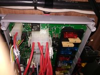
Second mod: A Thetford 3 way fridge consumes about 15 amps at 12 V DC while driving and this current has to pass through the PCB. Disconnect the white fridge connector from the PCB, the coil wires of a 30A automotive relay are connected in its place with two 1/4" slide-on tags (just visible in this image).

Take a pair of 6mm2 cables from the starter battery, the negative can be fitted into the fridge plug. Large Yellow 1/4" slide-on male tags take the 6mm2 cable and fit into plug. The positive fused supply connects to the relay N/O contact, the C is connected to the fridge plug observing polarity. If this mod is not carried out and the fridge is left connected as standard it would take its 15 amps from the 30 the B2B can supply, slowing the charging process and discharging the leisure battery when the engine is off.
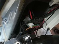
Third mod: At the base of the drivers side B pillar are the "Converters Connectors", I believe these are the same no matter what make of Fiat based motorhome you have. Disconnect the power connector {the connector with the big red and black wires). Leisure battery charging is now disabled.

Without this connection the Nord' control panel flashes a starter battery error, to cure this......
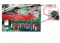
Fourth mod: The other end of the +ve wire from the above connector goes to J1 on the PCB, disconnect this, insulate it and stow. Make a link wire to connect PCB J1 to J2, with a length of 10mm2 wire and two 5mm tags.
Next connect the B2B pos and neg I/P to the starter battery with 16mm2 wire and a 60 Amp fuse as recommended by Victron. As I used the Non-Isolated B2B I only needed to run a single 16mm2 +ve wire direct to the +ve terminal of the leisure battery with another 60 Amp fuse as recommended by Victron.
Our van has a Nordelettronica NE287 battery charger fitted. After the above mods it only charges the leisure battery, I do have an Ablemail AMT 12-2 battery maintainer https://wildebus.com/product/ablemail-amt-12-battery-maintainer/ ,this trickle charges the stater battery when the leisure battery reaches a high enough state of charge. The NE287 was set for a flooded battery type at the factory, this is probably to protect the starter battery, I changed this to AGM.
I intend to fit a LiFePo4 battery in the future, I feel that the high charge current a LiFePo4 can draw could damage the PCB or the relay, the above changes with the B2B fixes that.
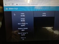
This image shows a ~30 Amp charge into the leisure battery which has a 77 SoC with the engine at tick-over. The B2B is in Bulk mode so current limited, the battery terminal voltage is at 13.62 volts. The voltage rose to 14.7 volts at a near 30 amps before going into float mode. The starter battery was at 14.21 volts for most of the time at idle, the B2B was producing 14.7 volts at its output in Absorption.

Once installed I recommend you check/adjust the "Engine shutdown detection" and "Input voltage lock-out". With the default setting the B2B was reluctant to disconnect when the engine was switched off. Having raised the levels the B2B has disconnected immediately the engine has been switched off.
I hope this helps some one in the future
Why did I fit a B2B? The Fiat starter battery is a flooded type lead acid battery, Roller Team fitted a single 95Ah Varta AGM battery as part of their habitation fit. A few times I had noticed that the leisure battery hadn't charged fully by the end of a drive, once was after a Motorway drive in rush hour traffic, basically a queue where the engine never really got going.
Varta recommend a Bulk charge voltage of 14.7 volt and the Fiat alternator output peaks at about 14.5 volts which by the time it gets to the leisure battery it has lost another couple of points. I will say that Roller Team have been very generous with wire sizes, other brands my be less well blessed. These days it's all about cost and weight reduction and big wires are heavy.
Delta Conversions are the UK sales distributor for Nordelettronica, I thought I'd see if they could offer any advice regards fitting a B2B, I got a single reply, "it can't be done", I asked another question but they didn't reply. Being told it can't be done made me look harder to see if I could prove them wrong. There wasn't much help on the net, one person had said to remove one of the surface mount resistor from the PCB to disable the split charge relay which is mounted on the PCB in the Nord' controller. An Italian owner had asked a similar question to me on an Italian forum but I couldn't find out whether he was successful or not.
The web has much info most useless but some it true and backed up with photos, there has been a small number of PCB track failures so one thing I wanted to do was off load some of the heavy current loads from the PCB.
So here are the modifications in order:
First mod: connect a 35mm2 cable from the leisure battery -ve to the Fiat starter battery ground point. The ground point is in the floor under your passengers right heel when sat in the passenger seat, it has the braided earth strap from the battery -ve. This made quite a difference with a smaller volt drop than the standard Roller Team earth return.
Second mod: A Thetford 3 way fridge consumes about 15 amps at 12 V DC while driving and this current has to pass through the PCB. Disconnect the white fridge connector from the PCB, the coil wires of a 30A automotive relay are connected in its place with two 1/4" slide-on tags (just visible in this image).

Take a pair of 6mm2 cables from the starter battery, the negative can be fitted into the fridge plug. Large Yellow 1/4" slide-on male tags take the 6mm2 cable and fit into plug. The positive fused supply connects to the relay N/O contact, the C is connected to the fridge plug observing polarity. If this mod is not carried out and the fridge is left connected as standard it would take its 15 amps from the 30 the B2B can supply, slowing the charging process and discharging the leisure battery when the engine is off.
Third mod: At the base of the drivers side B pillar are the "Converters Connectors", I believe these are the same no matter what make of Fiat based motorhome you have. Disconnect the power connector {the connector with the big red and black wires). Leisure battery charging is now disabled.

Without this connection the Nord' control panel flashes a starter battery error, to cure this......
Fourth mod: The other end of the +ve wire from the above connector goes to J1 on the PCB, disconnect this, insulate it and stow. Make a link wire to connect PCB J1 to J2, with a length of 10mm2 wire and two 5mm tags.
Next connect the B2B pos and neg I/P to the starter battery with 16mm2 wire and a 60 Amp fuse as recommended by Victron. As I used the Non-Isolated B2B I only needed to run a single 16mm2 +ve wire direct to the +ve terminal of the leisure battery with another 60 Amp fuse as recommended by Victron.
Our van has a Nordelettronica NE287 battery charger fitted. After the above mods it only charges the leisure battery, I do have an Ablemail AMT 12-2 battery maintainer https://wildebus.com/product/ablemail-amt-12-battery-maintainer/ ,this trickle charges the stater battery when the leisure battery reaches a high enough state of charge. The NE287 was set for a flooded battery type at the factory, this is probably to protect the starter battery, I changed this to AGM.
I intend to fit a LiFePo4 battery in the future, I feel that the high charge current a LiFePo4 can draw could damage the PCB or the relay, the above changes with the B2B fixes that.
This image shows a ~30 Amp charge into the leisure battery which has a 77 SoC with the engine at tick-over. The B2B is in Bulk mode so current limited, the battery terminal voltage is at 13.62 volts. The voltage rose to 14.7 volts at a near 30 amps before going into float mode. The starter battery was at 14.21 volts for most of the time at idle, the B2B was producing 14.7 volts at its output in Absorption.

Once installed I recommend you check/adjust the "Engine shutdown detection" and "Input voltage lock-out". With the default setting the B2B was reluctant to disconnect when the engine was switched off. Having raised the levels the B2B has disconnected immediately the engine has been switched off.
I hope this helps some one in the future
Last edited:

