Numpty installing a Mmpt solar controller

mikewroe

Full Member

Messages
74
Just about to install a solar setup on a bog standard motorhome. Before I start is there anything to be away of with regards to the mains on board battery charger. I am assuming I apply the full 12v habitation load to the solar controller but keep the 240v charge circuit upstream of the device. That is connected directly to the battery.
Controller is a Victron Mmpt 100/20.
Many thanks
 
The controller connects direct to the battery, make sure it has a fuse from panel wires before the unit if it does not have any, the onboard charger won't affect it.
 
I just run them as separate system entirely.

I fit the panel first and run the cables inside but leave the connection til last, fit the controller and connect to the battery first, cover panel (cardboard and a couple of bricks is enough) until safely connected & fuse the positive cable.
 
Sorry if I am am labouring the point. If I insert the controller so all the load is going through the device the mains charger will be attempting to charge back via the load output connector. This doesn't sound right to me.
 
It just works, the charger should see a charged battery and cut out when it's sunny.
 
Sorry if I am am labouring the point. If I insert the controller so all the load is going through the device the mains charger will be attempting to charge back via the load output connector. This doesn't sound right to me.
If you plan to connect the habitation electrics through the LOAD terminal on the Victron MPPT100/20, you should take note that the maximum current on that circuit is strictly 20A. If you exceed that, the circuit turns off.
Generally this is ok as you are unlikely to have that level of load, but if you have any DC devices on the output that have a bit of a surge on startups, you might find a problem. For example you cannot run a compressor fridge off the LOAD circuit. A Diesel Heater might cause issues depending on what else you might have running.

Also, depending on your general electrics setup, if you DO insert the controller in a certain position "so all the load is going through the device", fitting it in-between the Battery and the Electrics control Box (be it Sargent, Schaudt, CBE, or whatever), it will likely give you issues as the current from a charger would as you are pondering go INTO the LOAD, which is not what you want to be doing.

Basically your best bet is to forget the LOAD terminals are even there on the solar contoller if your Motorhome has otherwise got a bog-standard Electrical setup.
Battery => Battery
Solar => Solar Panels
LOAD => nothing!
 
I did look at some quite complicated setups when I did my first one, but I looked at it that the idea was to fit a panel and controller to charge the LBs, simple but effective, this latest one I had someone fit it for me and it's a bit of a mess to be honest, if I'd been fit enough I'm sure I could have done a much better and tidier job.
 
There are only 4 wires to connect so its rather easy. Some people however manage to get it wrong. You don't use the load terminal for anything. You connect two nice thick wires from the battery to the Solar Controller first. Then you connect two nice thick wires from the solar panel to the Solar Controller. The battery charger does not have anything to do with it. Each unit has a way of stopping the power flowing backwards. Its a bit like a one way valve. Let's water through one way but not the other. Instead of covering the panels you can do it in the dark or just have a couple of push connectors in the circuit. Decent cables are good otherwise you get a voltage drop on long runs.
 
I use 6mm2 cables with yellow pin terminals into the controller.

I had to to cut the plastic off on one van as there was no room so I used red and black shrink sleeving.
 
There are only 4 wires to connect so its rather easy. Some people however manage to get it wrong. You don't use the load terminal for anything. You connect two nice thick wires from the battery to the Solar Controller first. Then you connect two nice thick wires from the solar panel to the Solar Controller. The battery charger does not have anything to do with it. Each unit has a way of stopping the power flowing backwards. Its a bit like a one way valve. Let's water through one way but not the other. Instead of covering the panels you can do it in the dark or just have a couple of push connectors in the circuit. Decent cables are good otherwise you get a voltage drop on long runs.
You CAN use the Load output if you want to get a bit funky ;) I have all my own Hab electrics supplied from via the Load. It can be a good way to monitor the usage.
1681060003804.png

As far as "nice thick cables" go, you really don't need the kind of cables people like to think. For example, Pudsey mentions he used 6mm2 cables into his controller? You can't even FIT 6mm2 cables into the terminals of a Victron 100/20 controller, let alone need them.
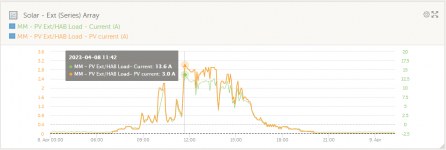
The maximum current you can expect to see into the Controller from the panels will be around 15A if you connect the multiple panels in parallel (if in series, the maximum current will be a lot less). A 1.5mm2 cable can handle that type of current ;) (little example below - just 3A into but 13.6A out))
1681061213842.png
I would go with either 2.5mm2 or 4mm2 cable generally for a 100/20 installation with parallel panels of upto 300W total. Probably the 4mm2 cable as the price difference is small between the two usually.
The voltage drop thing is a bit exaggerated as well often, TBH (sorry :( ). That example above ... I have checked the voltage at the panel array vs the voltage the controller is reporting, as well as the current (clamp meter on array vs controller current in report) and they are pretty well the same values despite having 50 feet of 1.3mm2 (16AWG) cable in the connection. I wouldn't specfically recommend either that gauge cable or that length of cable but when the panels are a distance, heavy cable can be a significant - and quite possibly unnecessary - expense.


As always, different folk take different approaches, but solar cable does tend to be over-egged when it comes to saying what must be used.
 
I used 6mm2 as I was planning more than one panel eventually I had three 100w planned, but 100w turned out to be about right with 220ah and then I lessened my needs too, but the yellow pin terminals made it a doddle as you say no way you'd get more than 4mm2 in easily, and they don't get chewed up either
 
Great advice thanks, I have now grasped the set up needed. As I have the bluetooth controller I would like to monitor the load in and out. To keep the habitation load under 20 amps I will connect the inverter directly to the battery as that's the only heavy, spikey load I believe there is.
To enable charging when on a site with EHU I plan to disconnect the CBE ? charger's output and re-root directly onto the battery. This appears quite easy as there is a h/d connector I can access. I assume the only downside would be that any 12v load is pulled directly from the battery as opposed to being fed from the CBE. I dont know the workings of the charger but guess it supplies power as well as chargers?
 
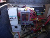
All my goodies are direct from the battery via the fuse box as above picture.
The charger is behind the fuse box & solar regulator votronic to the right, it does the les batts and 1ah to the starter bat.
 
To bring this post to a closure. I have just realised that I had forgotten about the alternators circuit that would also have been connected to my load connection.
I have resigned myself to just running the mmpt without any load connections just as Wildebus suggested early.
 
If you plan to connect the habitation electrics through the LOAD terminal on the Victron MPPT100/20, you should take note that the maximum current on that circuit is strictly 20A. If you exceed that, the circuit turns off.
Generally this is ok as you are unlikely to have that level of load, but if you have any DC devices on the output that have a bit of a surge on startups, you might find a problem. For example you cannot run a compressor fridge off the LOAD circuit. A Diesel Heater might cause issues depending on what else you might have running.

Also, depending on your general electrics setup, if you DO insert the controller in a certain position "so all the load is going through the device", fitting it in-between the Battery and the Electrics control Box (be it Sargent, Schaudt, CBE, or whatever), it will likely give you issues as the current from a charger would as you are pondering go INTO the LOAD, which is not what you want to be doing.

Basically your best bet is to forget the LOAD terminals are even there on the solar contoller if your Motorhome has otherwise got a bog-standard Electrical setup.
Battery => Battery
Solar => Solar Panels
LOAD => nothing!
Why do you say you cannot run a compressor fridge off the load output David? My fridge uses less power than the diesel heater on startup. I don’t run anything from load but know a few that do
 
Why do you say you cannot run a compressor fridge off the load output David? My fridge uses less power than the diesel heater on startup. I don’t run anything from load but know a few that do
A compressor fridge has a high surge which can exceed 20A. In normal running, no problem, but on startup another story. You may think the fridge is less than the heater, but you probably have not caught the surge (it only lasts a few seconds. The heater powerup is over 5 minutes)
This will illustrate the situation - look at the number in the top right and what happens around 40 seconds in ...
Times:
0:05 - Inverter Switched On
0:20 - Fridge Plugged in
0:30 - Fridge Door Opened (so Light comes on)
0:41 - Fridge Temp Dial turned to Max - Compressor In-rush Current comes on
0:45 - In-Rush Current ends

This is a 240V Compressor Fridge but the same thing happens on 12V compressor fridges.
Does a pure 12v compressor fridge do the same though? I could get mine to run on 240v by fitting a Mobilec 100W rectifier, the initial surge isn’t the charging of the rectifier is it?
 

Users who viewed this discussion (Total:0)

Back
Top