You are using an out of date browser. It may not display this or other websites correctly.
You should upgrade or use an alternative browser.
You should upgrade or use an alternative browser.
B2B Battery 2 Battery charger
- Thread starter xsilvergs
- Start date
wildebus
Full Member
- Messages
- 7,779
It's not so much Sargent as the British Motorhome makers deciding to adhere to an optional regulation where the european ones don't bother.I am so glad I don’t have a Sargent system with it’s annoying domestic shut off. By now they should know the difference between a caravan and a motorhome.
wildebus
Full Member
- Messages
- 7,779
EC325/328What model is your Sargent?
Chasn
Full Member
- Messages
- 64
I have some experience with the Sterling BB1260. I also found that the output was throttled as the unit temperature approached the 80degC limit. I checked with Sterling and they agreed that temperature can limit the output so I added fan cooling through the central vent at the top of the unit. This controls the temperature adequately but even when cool I rarely see more than 43A out of the rated 60A output. Not sure whether the other makes have the same issues but, provided that the battery can take it, it may be a good idea to over spec the B to B charger that you buy. If you use lithium batteries the charge limit is more about the alternator or B to B unit rather than the batteries.
wildebus
Full Member
- Messages
- 7,779
It is fairly simple to work out actually.I'd say that you'd need a pretty big battery bank to pull in 60A as a matter of routine.
But generally, a 60A B2B will run at full whack for a LiFePO4 bank over around 150ah until full, an advanced Lead Acid (PbC typically) bank over around 200Ah until around 80% full and a standard Lead Acid bank over something like 400Ah until around 80% full.
For most installs, a 60A is overkill and a 30A is probably the price/performance sweetspoot.
wildebus
Full Member
- Messages
- 7,779
That is not the case.
A good B2B will have a constant current all the time the battery is in Bulk mode (this is why it is also referred to as Constant Current mode).
And as the voltage continues to rise in that mode while the Current is constant, the B2B output is increasing as the voltage rises (P=I*V)
wildebus
Full Member
- Messages
- 7,779
I'll throw in some graphs I did from my own testing, to show this is not some theroretical copy and paste from "the internet", but actual real data ....That is not the case.
A good B2B will have a constant current all the time the battery is in Bulk mode (this is why it is also referred to as Constant Current mode).
And as the voltage continues to rise in that mode while the Current is constant, the B2B output is increasing as the voltage rises (P=I*V)
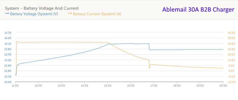
Battery Bank is Lead Acid AGM, with capacity of 380Ah@C20, taken down to 50% DoD prior to testing start. B2B is an Ablemail AMC12-30-30E, configured for Std Lead Acid Technology,
Orange Line is Current; Blue Line is Voltage
BT - Ablemail V_C by David, on Flickr
You see that for four straight hours the Ablemail Charger is outputing at maximum current (actually more. It is officially rated at 30A, but will put out slightly more) whilst the voltage is ramping up as the battery is getting charged.
It is only when the voltage has plateaued that the current starts to reduce (and the battery has moved from Constant Current to Constant Voltage aka Absorption mode).
After a couple more hours, the B2B goes into Float Mode (that is a programmed feature within the Ablemail B2B in fact after a set period of running, as it is not expected someone drives non-stop for over 6 hours)
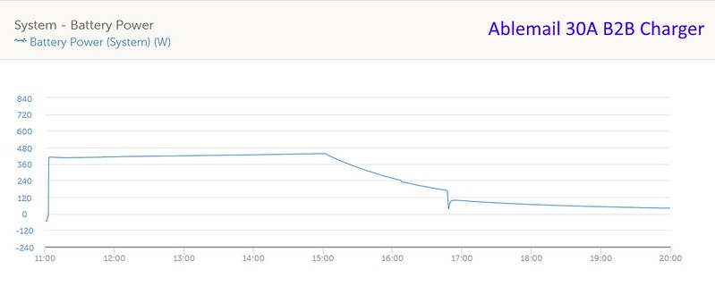
The same timeline showing the Power (watts) drawn by the B2B shows it is slightly increasing all the time as the output Voltage increases whilst the Current stays constant
BT - Ablemail Watts by David, on Flickr
(P=I*V ==>I is constant, V increases therefore P increases)
You can expect the same behaviour from any good B2B Charger. The Ablemail unit is exceptionally good as you can see from the quality of the current output. The Victron 30A Smart-Tr B2B exhibits the same kind of behaviour.
The Redarc 40A B2B unit I evaluated was pretty good as well but did have occasional glitches over the time scale which was a little disappointing, but still reasonable enough.
The above data is why I only directly recommend/supply/fit Ablemail or Victron B2Bs as I know from experience they deliver what they promise.
If you have a B2B where the current is always lowering as the voltage increases, then that basically is probably not a good B2B. If the output suddently lowers after a period, then it is probably the B2B dropping to a lower setting as it overheats. Again, not that great.
If the output fluctuates then that could be just a consequence of the Alternator output varying as engine speeds change, but once got started on a drive, unless it is very stop-start, the B2B maximum - especially at the smaller (sub 40A versions) - will be less than the current the Alternator is putting out so that should not be a limiting factor so the B2B fitted may play a part in this as well.
Last edited:
Markd
Full Member
- Messages
- 1,033
Great explanation and graphs.
Nicely reinforces your point about alternators primarily being a power source rather than a battery charger.
Nicely reinforces your point about alternators primarily being a power source rather than a battery charger.
wildebus
Full Member
- Messages
- 7,779
Thanks.Great explanation and graphs.
Nicely reinforces your point about alternators primarily being a power source rather than a battery charger.
And yes, Alternators are a mechanism or tool to charge a battery, but that does not make them a proper battery charger.
Maybe this analogy will help explain that point to others who don't understand....
This vehicle is being used to move a whole family around, but could you really call it a "people carrier"?

Last edited:
xsilvergs
Free Member
- Messages
- 240
Motivated by @wildebus post "Turbo-charging Motorhome Electrics" over on Motorhome Builder and his addition of a B2B to his Autotrail, here are my thoughts for incorporating a B2B in the Nordelettroica system fitted to our motorhome. Everything in the Nord' is fitted to a surface mount PCB making modification a little difficult, and if I get it wrong, expensive! So here are my 2 ideas for non-destructive modification. The coloured items in the drawings are my modifications, there is an unmodified drawing circuit diagram at the start of this topic. At present there is a single AGM but in the future I will swap the LiFePO4.
Fuses aren't shown for simplicity.
If anyone can see a simpler/better way or a flaw in my ideas please let me know, that's why I'm asking as it's to easy for me to miss the obvious.
First things first, no matter what, the fridge wiring will be changed and the supply taken from the Starter Battery on larger gauge wire, the Nord' board will just operate my additional relay.
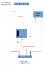
Now for the B2B wiring.
Least favourite idea is to add a large diode the to stop the the B2B from feeding back into the Starter Battery. Obviously there is a volt drop across the diode but I think everything should work as it has always although should the Leisure battery type be changed from AGM........
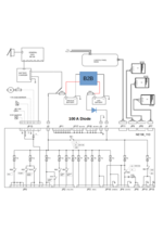
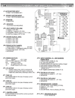
Now this to me appears to be a better idea and should work nicely with LiFePO4 batteries. The Starter Battery is disconnected from Nord' and the only loads that were supplied by the Starter Battery and now supplied by the Leisure Battery are the outside marker lights JP14 JP15 and even these could be shifted to the Starter Battery with a relay.
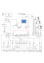
For info, Connectors.
Fuses aren't shown for simplicity.
If anyone can see a simpler/better way or a flaw in my ideas please let me know, that's why I'm asking as it's to easy for me to miss the obvious.
First things first, no matter what, the fridge wiring will be changed and the supply taken from the Starter Battery on larger gauge wire, the Nord' board will just operate my additional relay.

Now for the B2B wiring.
Least favourite idea is to add a large diode the to stop the the B2B from feeding back into the Starter Battery. Obviously there is a volt drop across the diode but I think everything should work as it has always although should the Leisure battery type be changed from AGM........

Now this to me appears to be a better idea and should work nicely with LiFePO4 batteries. The Starter Battery is disconnected from Nord' and the only loads that were supplied by the Starter Battery and now supplied by the Leisure Battery are the outside marker lights JP14 JP15 and even these could be shifted to the Starter Battery with a relay.

For info, Connectors.

xsilvergs
Free Member
- Messages
- 240
Thanks for looking at my post and commenting. My intention is, see diagram 1, to use the original fridge supply from the Nord' to control a relay reducing the 10-15 Amps down to less than 1 Amp for the relay coil.
On another forum (probably not allowed to mention it) someone suggested removing a resistor to disable RE1 the split charge relay. Removing RE1 is another option but there's always the risk when desoldering from the PCB. As the OP from the other forum never replied to a PM I asked I don't know how successful his mod was.
Last edited:
wildebus
Full Member
- Messages
- 7,779
If you went for the option of disconnecting the Starter from the Nord unit entirely, what knock-on effects would there be?
I am not familiar with that unit but am wondering about the following (which may or may not be applicable, so just thoughts here...)
Cannot charge the starter from the built-in mains charger. You have the AMT fitted but might want to do a complete charge sometime?
Display no longer reports starter battery info (if it used to) or allows use of it? (Is this important if so? Probably not really)
Adding connection as per red line would by-pass check for engine on signal, so assume it is always on? Apart from Fridge, which you are addressing, any other knock-on effects? (any functions that are prohibited when engine running end up being disabled? Or that SHOULD be disabled allowed to stay active? Looks like there is something to do with the 230V function at RE1?
xsilvergs
Free Member
- Messages
- 240
If you went for the option of disconnecting the Starter from the Nord unit entirely, what knock-on effects would there be?
I am not familiar with that unit but am wondering about the following (which may or may not be applicable, so just thoughts here...)
Cannot charge the starter from the built-in mains charger. You have the AMT fitted but might want to do a complete charge sometime?
Display no longer reports starter battery info (if it used to) or allows use of it? (Is this important if so? Probably not really)
Adding connection as per red line would by-pass check for engine on signal, so assume it is always on? Apart from Fridge, which you are addressing, any other knock-on effects? (any functions that are prohibited when engine running end up being disabled? Or that SHOULD be disabled allowed to stay active? Looks like there is something to do with the 230V function at RE1?
@wildebus
Thanks for your time to look through my post, I'll try and address your questions with my thoughts, hopefully you'll agree, if I haven't made a massive oversight. If you see a flaw please let me know.
Charging of Starter Battery: If I go to Lithium I would buy a new charger, the EasyPlus you cover takes my fancy. The original charger could be reconnected to charge the Starter Battery only.
230V function at RE1: I can't confirm this thought at the moment but I wonder if the Charger which is connected to JP13-3 may be the signal the Nord' takes as the 230V connected. I often disconnect the AC input to the Charger, when the Solar/Inverter is powering the fridge. When I can get in the van I'll test my theory.
In some ways the big 100 Amp diode seems a good answer, the B2B can't self-feed itself or overcharge the Starter Battery. Should the B2B fail there is an alternative charge path through the diode. The fridge would not be a drain on the B2B as it would have its separate supply. The higher output from the B2B would be OK until it goes into Float, at the this point could the Alternator try to charge the Leisure battery (there would be the volt drop across the diode which may take low enough to stop any charging).
I had considered putting the B2B in the line between the Starter Battery and the Nord's J1 connection, this could be fine with a 30 Amp B2B but would the PCB survive with a 60 Amp B2B and Lithium? Also if RE1 opened how does a B2B respond when the path to the battery it's charging is suddenly removed?
I have found this Italian forum.camperonline.it I've run it through Google Translate, probably better for the Italian reader amongst us.
I do appreciate everyone's time and comments, it's great to have others to bounce ideas off. These forums are so much better than Facebook etc where you only get abuse and stupid comments, thanks @Geeky Philip .
wildebus
Full Member
- Messages
- 7,779
Sounds like a plan. As you know, I like the Victron Multiplus's and the EasyPlus (which is a Multiplus 1600 plus a Consumer Unit Combo for less money than a Multiplus on its own) is a very nice unitThanks for your time to look through my post, I'll try and address your questions with my thoughts, hopefully you'll agree, if I haven't made a massive oversight. If you see a flaw please let me know.
Charging of Starter Battery: If I go to Lithium I would buy a new charger, the EasyPlus you cover takes my fancy. The original charger could be reconnected to charge the Starter Battery only.
Ref the disconnect to the charger when Solar is active. With the EasyPlus I am using the BMS Assistant so I can disable the Charging function of the MultiPlus whenever I want to. That way I can keep the AC live at the same time if I want to. Currently it is just driven by a remote relay but you could easily drive it by other means I am sure. I have that in place ready for when Solar comes into the picture (maybe drive it from the Victron MPPTs load output programmed in some way, but you have a host of options in your monitoring setup).230V function at RE1: I can't confirm this thought at the moment but I wonder if the Charger which is connected to JP13-3 may be the signal the Nord' takes as the 230V connected. I often disconnect the AC input to the Charger, when the Solar/Inverter is powering the fridge. When I can get in the van I'll test my theory.
I do like the idea of a redundancy (I snipped a wire to disable my intergrated split-charge but might add a switch so I can re-enable if I had a need to).In some ways the big 100 Amp diode seems a good answer, the B2B can't self-feed itself or overcharge the Starter Battery. Should the B2B fail there is an alternative charge path through the diode. The fridge would not be a drain on the B2B as it would have its separate supply. The higher output from the B2B would be OK until it goes into Float, at the this point could the Alternator try to charge the Leisure battery (there would be the volt drop across the diode which may take low enough to stop any charging).
If you assume a 0.7V drop on the diode, I guess potentially an alternator at 14V or so could start putting some charge into a charged battery bank if you have some load on it that takes away the 'surface charge'? would that be a concern? You could add in a relay in series and so manually (or automatically from an appropriate signal) disable to stop it happening?
Must say I would have concerns about higher currents than designed going through PCB tracks. The Nord might be different, but the typical PCB for any product is not usually overendowed with thick copper tracking.I had considered putting the B2B in the line between the Starter Battery and the Nord's J1 connection, this could be fine with a 30 Amp B2B but would the PCB survive with a 60 Amp B2B and Lithium? Also if RE1 opened how does a B2B respond when the path to the battery it's charging is suddenly removed?
Maybe ask Jonathan about how a B2B acts when the load is removed? I think I have had a similar discussion when looking at my VSR/B2B combo where that happens but was quite a while ago when we were just chewing the fat. Nothing untoward ever happened, but worth an chat maybe?
I have found this Italian forum.camperonline.it I've run it through Google Translate, probably better for the Italian reader amongst us.
I do appreciate everyone's time and comments, it's great to have others to bounce ideas off. These forums are so much better than Facebook etc where you only get abuse and stupid comments, thanks @Geeky Philip .
