Led rear lights

Problem with full led replacement unit is if it goes down which they do then expensive replacement, a led bulb is cheap and easy to carry in tool kit.
Thanks I will get a few together but I do have a replacement full unit for either side if I need them.
 
It's actually against the law to replace any e-marked halogen bulb with LED, none of which can be e-marked. But the MOT only checks headlights. As long as the colours of rear lights and indicators are good, you should be fine.
I still have some 5ohm resistors from attempting the same fix on a Merc Hymer. It didn't work! But the LEDs I replaced the pathetic DRL bulbs with worked with no problems and no resistor!
 
Not changed any halogen bulbs just the whole of the rear light clusters as it is a 2003 van only the headlights would be halogen so no worries there
The rear lights were old 5 and 10 amp bulbs. I doubt any of then had an e mark

The rear lights looked like the back of a small box trailer.
 
Well after a hit and run I have had to replace one of the rear light clusters. In fact changed both as I was given two pairs of led lights.
All the wiring had to be stripped back to the basic fives wires

Black earth
Blue indicators
Red brake lights
Yellow side lights
White reversing lights.

The question is where has the fog light wire gone

Or is the white wire used for both the reversing light and the fog light ….

ModelFiat ducato 2003. Mk 2Year2003
Quote Reply
Report Edit
 
Last edited:
Not changed any halogen bulbs just the whole of the rear light clusters as it is a 2003 van only the headlights would be halogen so no worries there
The rear lights were old 5 and 10 amp bulbs. I doubt any of then had an e mark

The rear lights looked like the back of a small box trailer.
Watts not amps, 5 for running light 21 for brake reverse & winkers.
My led were so bright i had to paint the t light ones red as mot sayed to white/bright and failed me.
 
Now sorted and fully working

The white wire there are two of them a long way up the wiring loom

All the other colours there is only one of each At the back of the van


The red /. Yellow. . / black ../ blue then are joined together to split both ways to both light clusters. But the white wires one goes near side the other offside.

The off side one IS for the fog light. Uk requirement
The near side is for the reversing lights. Uk requirement

However both have a reversing light in the cluster so a link was made from one to the other so both reversing lights were working .
The white fog light wire was still connected to the non working reversing light.

The reversing lights still work now the white wire to the off side has been cut.

So the white was not working on the reversing lights
Hence having tested it with a bulb it’s the fog light.

Now got both fog lights working
And both reversing lights.
And everything else is fully working.
 
Whar type, size resister would I need to stop sparks when connecting a 1500 wat inverta to battery
?
You'd need to leave the inverter permanently connected via the resistor in order to keep the internal capacitor charged, the problem with this is that while you're keeping the capacitor charged the inverter is also drawing standing current.
If your inverter takes 1A standing current and you used a 1 ohm resistor across the switch contact then this would keep the capacitor in the inverter charged up to 1v lower than battery voltage(approx 11v) so you'd only get a very small spark when you made the connection proper because the capacitor would remain 11/12ths charged.
Problem with this is you'd have 11/12ths current still flowing so you'd hardly benefit from switching the inverter 'off'.
What's the issue with the spark anyway? You're not repeatedly connecting and disconnecting are you? If you are then there's no need, just use the on off switch at the inverter,
 
Last edited:
You'd need to leave the inverter permanently connected via the resistor in order to keep the internal capacitor charged, the problem with this is that while you're keeping the capacitor charged the inverter is also drawing standing current.
If your inverter takes 1A standing current and you used a 1 ohm resistor across the switch contact then this would keep the capacitor in the inverter charged up to 1v lower than battery voltage(approx 11v) so you'd only get a very small spark when you made the connection proper because the capacitor would remain 11/12ths charged.
Problem with this is you'd have 11/12ths current still flowing so you'd hardly benefit from switching the inverter 'off'.
What's the issue with the spark anyway? You're not repeatedly connecting and disconnecting are you? If you are then there's no need, just use the on off switch at the inverter,
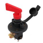
I've seen mention of this resistor thing a few times. TBH I've never bothered even with a setup where I am controlling the power via the 12V supply.
If you did want to "precharge" AND remove 12V when not in use, you could use a 1+2 isolation switch, with one position including the resistor. So go from off to 1 for a few seconds then go to 2 to use, for example.
Yes but what size type of resistor would I need ?
 
Fitted led rear lights .
The indicators now flash very fast.

The law states between 60 and 120 flashes a minute

How to fool the system that now thinks it has a blown bulb.

Any ideas.
It needs a resistor in the system!
 
I've seen mention of this resistor thing a few times.
I'd never come across it before so I googled it to find out what the fuss was all about. The theory is that the inrush current into to capacitors in the inverter could be large enough to trip the current limit in a lithium BMS. ...... yeah possibly maybe depending on the design of the BMS and the size and ESR of the capacitor/ capacitors. Some suggestions of initially connecting up via a pencil (the graphite core is a resistor), but personally I'd just use a couple of foot or more of thin hook up wire.
 
Could it be these.


Those look like they'd stop the fast flashing, but they'd also prevent the function of the fast flashingc

The fast flash is supposed to alert you to the fact that one of your indicators isn't working.

With these resistors fitted you'd not be alerted if a lamp fails.
 
Those look like they'd stop the fast flashing, but they'd also prevent the function of the fast flashingc

The fast flash is supposed to alert you to the fact that one of your indicators isn't working.

With these resistors fitted you'd not be alerted if a lamp fails.
I usually check before we go anywhere so that’s not a problem. Plus we carry spare bulbs.
 
I usually check before we go anywhere so that’s not a problem.
Not only do I not do that, but I don't know anyone who does. Do you check your indicators every time you drive? Seems an awful lot of hassle for very little gain.
 
Not only do I not do that, but I don't know anyone who does. Do you check your indicators every time you drive? Seems an awful lot of hassle for very little gain.
I do, you are responsable for doing so, ok they can fail when out but best look before a trip out, you have to do this in the army.
 

Users who viewed this discussion (Total:0)

Back
Top